Connectivity Bar (if Available)
This section is only relevant when a connectivity bar is installed on the device.
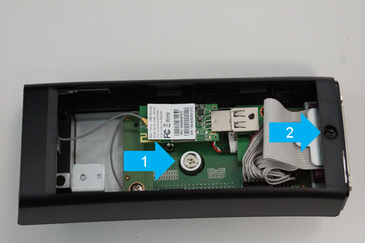
- Loosen the screw (1) to detach the connectivity bar from the device.
- Loosen the screw (2) to remove the plastic cover.
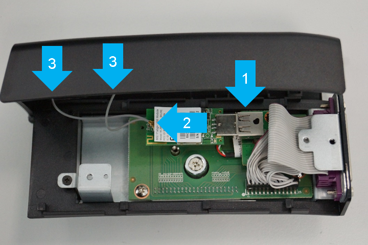
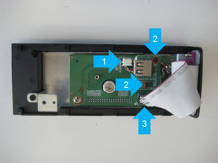
- Disconnect the Wi-Fi module from the USB port (1).
- Disconnect the antennas from the Wi-Fi module (2).
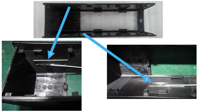
- Detach the antennas from the inside of the plastic cover (3).
- Pull out the cable (1).
- Loosen two screws (2) and remove the USB board from the main board.
- Pull off the serial port ribbon cable (3) from the main board.
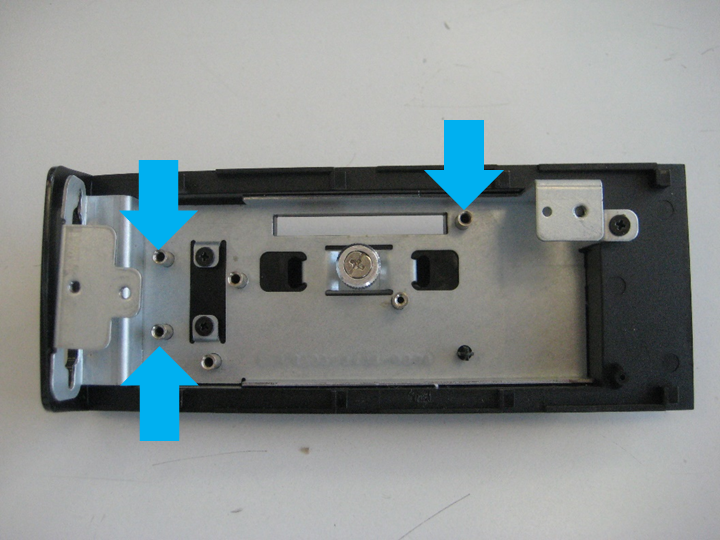
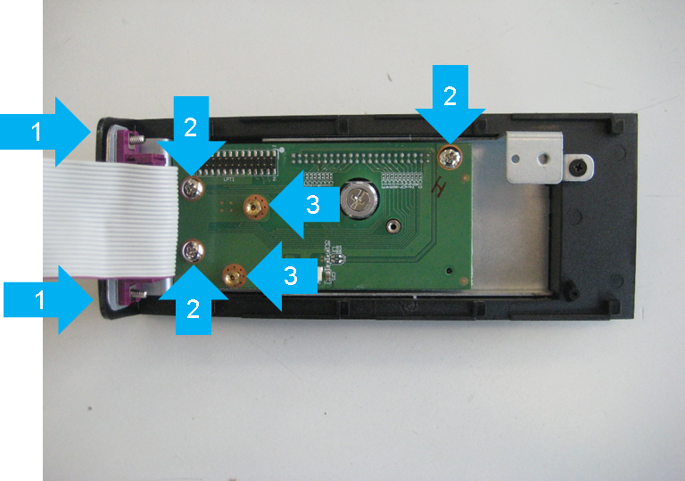
- Loosen two screws (1) and remove the parallel interface.
- Loosen three screws (2).
- Loosen two spacer bolts (3) and remove the main board.
- Loosen three screws and remove the metal base plate from the plastic cover.